Stk413-430 Circuit Diagram Upd -
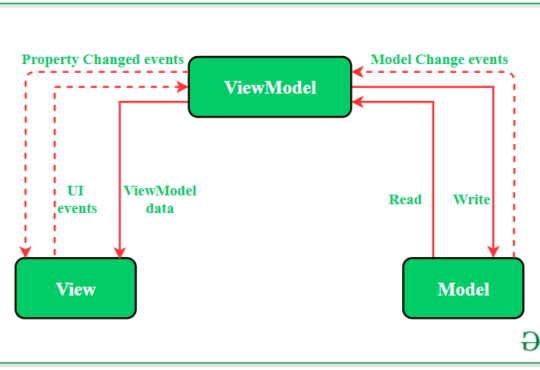
Pin 12 (Bootstrap) ------------------------C3 (+)----+ | Pin 10 (Output L) --------------------+--------+ | | | | R4 (4.7Ω) | | | | +--------+ | | | | C4 (0.1µF) | | | | +--------+----+--- to Speaker (+) | Speaker (8Ω) | Ground
Below is a representing typical stereo application for STK4132, STK430, STK432, etc.
While you cannot repair the inside of a hybrid IC, understanding the internal circuit helps you diagnose external failures. stk413-430 circuit diagram
The STK413-430 operates using a split (dual) power supply, allowing it to drive loads with high fidelity and minimal noise. Pin Configuration:
Here is a practical circuit schematic you can build on a perfboard or design a PCB for. Pin Configuration: Here is a practical circuit schematic
Receives line-level signals (around 250mV to 1V) through decoupling capacitors to filter DC noise.
: To integrate this module into a project, you must connect the audio source to the input pins and speakers to the output pins, ensuring the speaker impedance matches the module's specifications. : To reduce audio ripple and noise, it
: To reduce audio ripple and noise, it is recommended to place large electrolytic bypass capacitors (e.g., >4700µF) near the power supply terminals.
Popular among hobbyists for building custom 100W+ bass-heavy stereo amplifiers.
The external circuit diagram for an STK413-430 is relatively simple compared to discrete transistor amplifiers. The complexity is hidden inside the module. Below is a breakdown of the essential blocks found in the application circuit.
The gain of the STK413-430 is set by the ratio of the feedback resistor (Rf) to the resistor to ground (Rg). In the standard application: